PROBLEM SOLVING AND PYTHON PROGRAMMING
UNIT I – ALGORITHMIC PROBLEM SOLVING
Introduction to problem solving
A computer is an electronic device capable
of executing programs. A program is an organized set of instructions. Each
program performs a specific task when executed by the computer. A program is
usually written in a programming language like C, C++, Java, Python etc.
The primary aim of a computer
program is to solve a given problem. Any problem, irrespective of the
programming language in which it is written, has three aspects
1. Output – What is
the desired outcome of the program?
2. Input – What is
the available data / information?
3. Process – How
the input information can be processed / manipulated to produce the desired
output?
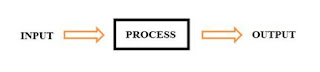
Figure 1.1: Execution of a Program.
Algorithm
An algorithm is a step-by-step
procedure to solve a given problem. It is a well-defined computational procedure
that takes some values as input, manipulates them using a set of instructions
and produces some values as output and terminates in a finite amount of time. An
algorithm, when formally written in a programming language is called a program,
or code.
Derivation of an algorithm that solves
the problem and conversion of the algorithm into code, together, is known as Algorithmic
Problem Solving.
Characteristics of an Algorithm
1. Well defined –
the steps are in a clear order
2. Unambiguous and
exact – the operations in the algorithm must be precisely described such that
they are understood by a computing agent without further simplification and
there remains no uncertainty
3. Effectively
computable – the computing agent can actually carry out the operation and
provide the correct answer to the problem
4. Terminate – The
purpose of an algorithm is to solve a problem. If the program does not stop
when executed, we will not be able to get any result from it. Therefore, an
algorithm must contain a finite number of steps in its execution.
5. General – An
algorithm must solve every instance of the problem. For example, a program that
computes the area of a rectangle should work on all possible dimensions of the
rectangle, within the limits of the programming language and the machine.
Method for Developing an Algorithm
1. Define the
problem: State the problem you are trying to solve in clear and concise terms.
2. List the Inputs
(information needed to solve the problem) and the outputs (what the algorithm
will produce as a result)
3. Describe the
steps needed to convert or manipulate the inputs to produce the outputs. Start
at a high level first, and keep refining the steps until they are effectively
computable operations.
4. Test the
algorithm: choose data sets and verify that your algorithm works
Building blocks of algorithms
Any algorithm can be constructed
from just three basic building blocks. These three building blocks are
Sequence, Selection (Branching), and Repetition (Looping / Iteration) and are
collectively called as Control Structures. Control structures control
the direction of flow of the program. It determines how a computer will respond
when given certain conditions and parameters.
Decision steps
Selection and repetition statements
typically involve decision steps based on an expression evaluation. Expression
may involve numeric value, arithmetic, logical and relational operators.
Decision steps are commonly called as test conditions.
In case of arithmetic operators, expression
that evaluates to a value can be interpreted as a true / false condition. The
rule is: If an expression evaluates to 0, its truth value is false and if
an expression evaluates to non-zero value, its truth value is true. Example
if a = 7, and b = 5,
|
Expression
|
Value
|
|
a
|
True
|
|
a – b
|
True
|
|
a – 7
|
False
|
Relational operators evaluate to a
Boolean value. Example if a = 5, and b = 3, then (a > b) will evaluate to
true. Similarly (a < b) will evaluate to false. Logical operators are
generally used to combine multiple conditions in the same expression. It may
involve any types of operators. Example a = 5, b = 7 & c = 3
|
Expression
|
Value
|
|
(a > b) AND (a > c)
|
True
|
|
(a + b) OR (a – c)
|
True
|
Sequence Structure:
The sequence structure is the
default structure. It contains a sequence of statements placed one after the
other and is executed in the same order.
Selection Structure:
Selection structure is used for
choosing between two or more alternative blocks of code. It is a binary decision
based on whether an expression (also called as test condition) evaluates to
TRUE or FALSE. Given two alternative blocks, if the test condition evaluates to
true, one of the two branches is explored; if the condition is false, the other
alternative is taken. The commonly used selection structures in any programming
language are ‘IF’, ‘IF – ELSE’ and ‘SWITCH’
IF structure: if the condition evaluates to
true, the statements in the block will be executed. Else it will be skipped and
the program continues its execution from the statement after the end if
statement.
Syntax:
if condition then
(statements)
end if
IF – ELSE Structure: Binary condition where
only one block of statements will be executed. If the condition evaluates to
true, the statements in the if-block will be executed. If the condition
evaluates to false, the statements in the else block will be executed.
Syntax:
if condition then
(statements)
else
(other statements)
end if
IF – ELSE – IF Structure: By using if-elseif-else,
it is possible to combine several conditions. Only the statements following the
first condition that is found to be true will be executed. All other statements
will be skipped.
Syntax:
if condition then
(statements)
elseif condition then
(more statements)
elseif condition then
(more statements)
...
else
(other statements)
end if
Switch Structure: This is a multi-way
branching statement, where, based on a condition, the control is transferred to
one of the many possible points. Keywords used in programming languages to
implement switch statement include switch, case, select or inspect.
This is implemented as:
switch (value) then
case value-1: // Statement block
case value-2: // Statement block
case value-3: // Statement block
…
default: // statement block
end switch
Repetition Structure:
Repetition structure is used for
looping, i.e. repeating a block of code multiple times in a row. It is a
construct where statements can be executed repeatedly until a condition
evaluates to TRUE or FALSE. It is represented by the ‘while’, ‘do-while’ and
‘for’ constructs in most programming languages.
WHILE Structure: The while construct consists
of a block of code and a test condition. The test condition is evaluated, and
if it evaluates to true, the code within the block is executed. This repeats
until the test condition becomes false. Because the while
loop checks the test condition before the block is executed, the while control
structure is often also known as an entry-controlled loop. If the test
condition evaluates to false the first time, the statement block may never be
executed.
Syntax: while
(test-condition) then
// Statement block
end while
DO – WHILE Structure: The do while construct
consists of a statement block and a test condition. First, the code within the
block is executed, and then the condition is evaluated. If the condition is true the code within the block is executed
again. This repeats until the condition becomes false. Because do
while loops check the condition after the block is executed, the control
structure is often also known as an exit-controlled loop. In contrast to while
loop even if the test condition evaluates to false the first time itself, the
statement block is executed at-least once.
Syntax: do
// Statement block
while (test-condition)
FOR Structure: While and do-while loop are
used in situations where the number of times the loop is to be executed is
unknown. For structure in contrast is used in situation where number of times
the loop is to executed is deterministic. The general syntax of the For
structure contains an initialization value, a test condition and an increment
value.
Syntax: for
(initialization; Test condition; increment)
//
statement block
End
for;
Iteration and Recursion:
One complete execution of a loop is
called iteration. Unbounded loops (while and do-while) refer to those whose
number of iterations depends on the eventuality that the termination
condition is satisfied. If the condition for the termination of the loop is not
satisfied after some finite number of iterations it ends up as an infinite
loop. Bounded loops (for) refer to those whose number of iterations is known
before-hand.
A recursive algorithm is an
algorithm which calls itself with smaller input values, and which obtains the
result for the current input by applying simple operations to the returned
value for the smaller input. More generally if a problem can be solved
utilizing solutions to smaller versions of the same problem, and the smaller
versions reduce to easily solvable cases, then one can use a recursive
algorithm to solve that problem.
Nested Structures:
Combining the use of these control
structures, for example, a loop within a loop (nested loops), a branch within
another branch (nested if), a branch within a loop, a loop within a branch, and
so forth, is not uncommon. Complex algorithms may have more complicated logic
structure and deep level of nesting.
Example 1: Algorithm to find minimum, maximum & average of
list of numbers
1. First, initialize
sum to zero, min to a very big number, and max to a very small number.
2. Then, enter the
numbers, one by one.
3. For each number
that you have entered, assign it to num and add it to the sum.
4. At the same
time, compare num with min, if num is smaller than min, let min be num instead.
5. Similarly,
compare num with max, if num is larger than max, let max be num instead.
6. After all the
numbers have been entered, divide sum by the numbers of items entered, and let
avg be this result.
7. End of
algorithm.
Example 2: The modern Euclidean algorithm to compute
the GCD (Greatest Common Divisor) of two integers:
1. Let A and B be
integers with A > B ≥ 0.
2. If B = 0, then
the gcd is A and the algorithm ends.
3. Otherwise, find
q and r such that
A = qB + r where
0 ≤ r < B
Note that we have
0 ≤ r < B < A and gcd(A,B) = gcd(B,r).
Replace A by B, and B by
r. Go to step 2.
PSEUDOCODE
Pseudocode or Program Design Language
The word "pseudo" means
"false," so "pseudocode" means "false code." Pseudocode
is one of the initial processes in the program development. It is the outline
of a program written in natural language that precisely describes the steps to
be taken to complete a program. It is an informal way of describing the key
principles of a program making it easier to understand the underlying logic and
flow of the program.
Pseudocode provides an efficiently
detailed yet readable description of what a computer program is expected to do.
It avoids language-specific elements and is written such that the desired
programming code can be generated almost automatically from each statement. In
computer program development, pseudocode is extensively used for sketching out
the structure of the program before the actual coding takes place. Since the
logic and flow of the program and data are already defined, the programmer can
focus on the coding, resulting in faster code development.
Basic
Guidelines to create pseudocode:
1. Do not use
language-specific commands. Pseudocode should be universal and written such
that it can be translated into any language.
2. Write only one task
or statement per line. Including too much information on one line can be
confusing and increases the possibility of errors.
3. Capitalize
keywords. Example - 'Read,' 'Write,' or 'Display'. This helps to identify key
commands when coding in a specific language.
4. Use proper
indents in control structures to make it easier to read the program and
identify the flow of the program.
Advantages
of pseudocode
1. Easy to write:
Pseudocode is language independent. It does not use any programming language
syntax. It uses natural language and is hence can be written easily and quickly
in any word processor.
2. Easy to: Programming
languages are difficult to read for most people, but pseudocode allows
nonprogrammers, such as business analysts, to review the steps and confirm that
the proposed code matches the client requirements.
3. Easy to read,
understand check for errors: Pseudocode is both detailed and readable. It
can be checked by designers and programmers to study the program / data flow
and ensure that it matches the design specifications.
4. Error Check:
Pseudocode provides an additional level at which inspection can be performed.
It helps to check for conceptual errors and trap defects before they become
code. This also increases the product reliability.
5. Easy to
convert to program: Pseudocode is an outline of the program. The format of
pseudocode is similar to that of the programs. Both pseudocode and program
consists a set of sequential statements and use defined set of keywords.
Therefore, pseudocode can be converted to a full-fledged program using the syntax
any programming language.
6. Impose increased
discipline on the process of documenting the design.
7. Helps in faster
code development, since the logic and program / data flow are already defined.
8. Comparison with
flow chart:
a. Flowchart may
run for multiple pages. Pseudocodes are more compact.
b. Not easy to
modify a flowchart. Can easily make changes in pseudocode.
Limitations of Pseudocode
1. There is no
defined standard for writing pseudocode. Hence pseudocode is by nature
unstructured and programmers may use their own styles.
2. While pseudocode
is easy to read, it is not visual. It does not provide as good a map for the
programmer as a flowchart does.
3. For a beginner,
it is easier to follow complex logic when drawn as a flowchart, rather than
when written in pseudocode.
4. Since pseudocode
focus on detailed description, a lot of practice and concentration is required
to write pseudocode as compared to flowchart
5. Creates an
additional level of documentation to maintain.
Guidelines
for writing pseudocode:
1. State the name
of programmer
2. State the date
3. State the name
of the subroutine.
4. Give a brief
description of the function of the subroutine/program.
5. Input: State the
names of the input variables, their types, and give a brief description for
each.
6. Output: State
the names of the input variables, their types, and give a brief description for
each
7. Algorithm: Generally
pseudocode is written between begin and end statements. A comment entry is used
to provide information about the steps used in the pseudocode. Commonly used
keywords in pseudocode to denote various programming process are
§ Comment :
//
§ Input :
READ, GET, OBTAIN, PROMPT, ACCEPT
§ Output :
PRINT, DISPLAY, SHOW
§ Initialize :
SET, INITIALIZE
§ Compute :
COMPUTE, CALCULATE
§ Add one :
INCREMENT
§ Function call : CALL
<Subroutine_name>
Common Operator Symbols in Pseudocode
The following table shows some of
the common operators used in writing pseudocode.
|
Type of
operation
|
Symbol
|
Example
|
|
Arithmetic
|
+,
−, ×, /, mod
|
Area ← length x breadth
|
|
Relational
or
Comparison
|
=,
≠, <, >, ≤, ≥
|
a ≤
b
|
|
Logical
|
and, or
|
a > b
and a > c
|
|
Assignment
|
←
or :=
|
c ← 2πr, c := 2πr
|
|
Floor/ceiling
|
⌊, ⌋, ⌈, ⌉
|
a ← ⌊b⌋,
a ← ⌈b⌉
|
|
Sums,
products
|
∑
∏
|
h ←
|
Table 1.1: Operators in pseudocode
Pseudocode Language Constructs
1. Input / Output
a.
Input: Get var1, var2, ...
b.
Output: Display var1, var2, ...
c.
Initialize: c := 5, pi ← 3.142
2. Computation
/ Assignment
a.
Compute var1 as the sum of x and y
b.
Assign expression to var2
c.
Increment counter1
3. Selection
a.
Single-Selection IF
i. IF
condition THEN (IF condition is true, then do subordinate statement 1, etc. If
condition is false, then skip statements)
1.
statement 1
2.
etc.
b.
Double-Selection IF – ELSE
i. IF
condition THEN (IF condition is true, then do subordinate statement 1, etc. If
condition is false, then skip statements and execute statements under ELSE)
1.
statement 1
2.
etc.
ii. ELSE
(else if condition is not true, then do subordinate statement 2, etc.)
1.
statement 2
2.
etc
c.
SWITCH expression TO
i. case
1: action1
ii. case
2: action2
iii. etc.
iv. default:
action
4. Repetition
a.
FOR structure (a specialized version of WHILE for repeating
execution of statements a specific number of times)
i. FOR
bounds on repetition
1.
statement 1
2.
etc.
b.
WHILE condition (while condition is true, then do subordinate
statements)
i. statement
1
ii. etc.
c.
DO – WHILE structure (like WHILE, but tests condition at the end
of the loop. Thus, statements in the structure will always be executed at least
once.)
i. DO
1.
statement 1
2.
etc.
ii. WHILE
condition
Example: Pseudocode to find the minimum, maximum,
and average of a list of numbers
Programmer: IT_Dept
Date: 01.07.2017
Name: Number_manipulation
Function: Find minimum, maximum
and average in a list of numbers.
Input: List of numbers
Output: minimum, maximum, and
average of the given list of numbers.

FLOWCHARTS
Flow charts
Flowchart is a graphical tool that
diagrammatically depicts the steps and structure of an algorithm or program. A
flowchart consists of a collection of symbols. Some of the frequently used
symbols are explained below.
§ Terminal symbols
and Predefined process symbols
o All flow charts
start with a Terminal or Predefined Process symbol.
o Only one flow
line is used with these symbols.
o Terminal
symbols indicate the start or end of a program.
|
|
Figure 1.2: Terminal symbol
o Predefined
process symbols are used to invoke a subroutine or an interrupt program.
|
|
Figure 1.3: Predefined process symbol
§ Flow lines
o Collection of arrows
that indicate the direction of the progression of the program. Intersection of
flow lines should be avoided to make the flow chart more effective
 |
Figure 1.4: Flow lines
§ Input / Output
Symbols
o Represents
input and output of data
|
|
Figure 1.5: Input / Output symbol
|
|
Figure 1.6: Manual Input Symbol
§ Process symbols
o Represents any
type of internal operation, including data transformation, data movement, logic
operation, etc.
o Only one flow
line should exit a process symbol.
 |
Figure 1.7: Process symbol
§ Documents
o Indicates data
that can be read by people, such as printed output.
 |
Figure 1.8: Single Document symbol
 |
Figure 1.9: Multiple Document symbol
§ Decision symbols
o Usually, evaluates
a condition or statement and branches depending on whether the evaluation is
true or false
o Only one flow
line should enter a decision symbol. But two or three flow lines may leave the
decision symbol.
 |
Figure 1.10: Decision symbol
§ Manual loop:
o Indicates a
sequence of commands that will continue to repeat until stopped manually
 |
Figure 1.11: Manual loop Symbol
§ Delay
o Indicates a
delay in the process
|
|
Figure 1.12: Delay Symbol
§ Connector symbols
o Connects sections
of the flowchart, so that the diagram can maintain a smooth, linear flow.
o Connectors are commonly
used to connect breaks in the flowchart. Examples include:
§ From one page to
another page.
§ From the bottom of
the page to the top of the same page.
o In case of
complex flow charts, connectors are used to reduce the number of flow lines.
§ Example – An upward
flow of more than 3 symbols
 |
Figure 1.13: Connector symbol
§ Off Page Connector
o Creates a cross
reference and hyperlink from a process on one page to a process on another
|
|
Figure 1.14: Off Page Connector
§ Annotation
o Provides
additional information about a flow chart symbol. Generally used to describe
the data or process more clearly
|
|
Figure 1.15: Annotation symbol
§ Magnetic disk
o Indicates a
list of information with a standard structure that allows for searching and
sorting
|
|
Figure 1.16: Magnetic disk symbol
§ Stored data
o Indicates any
type of stored data
 |
Figure 1.17: Stored Data Symbol
§ Internal storage
o Indicates an
internal storage device
 |
Figure 1.18: Internal
Storage Symbol
§ Collate
o Indicates an
step that organizes data into a standard format
 |
Figure 1.19: Collate
Symbol
§ Merge
o Indicates a
step that merges multiple sets into one
 |
Figure 1.20: Merge Symbol
§ Sort
o Indicates a
step that organizes items list sequentially
 |
Figure 1.21: Sort Symbol
Flowchart for control structures
Sequence Structure:

Figure 1.22: Flowchart for
Sequence structures
Selection structures:
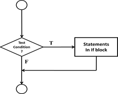
Figure 1.23: Flowchart – If structure
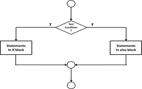
Figure 1.24: Flowchart – If – else
Structure
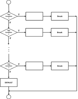
Figure 1.25: Flowchart – Switch Structure
Repetition Structures:
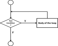
Figure 1.26: Flowchart –
While Loop
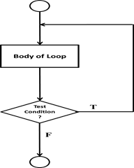
Figure 1.27: Flowchart – DO – While Loop
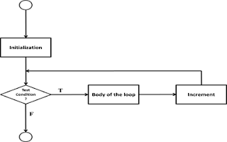
Figure 1.28: Flowchart – For Loop
General rules for drawing flowcharts
1. Flowcharts
should be clear, neat and easy to follow.
2. Flowcharts are
drawn such that flow generally goes from top to bottom.
3. All flow charts
start with a Terminal or Predefined Process (for interrupt programs or
subroutines) symbol.
4. All flowcharts
end with a terminal or a contentious loop.
5. All symbols of
the flowchart are connected by flow lines
6. Flow lines enter
the top of the symbol and exit out the bottom, except for the Decision symbol,
which can have flow lines exiting from the bottom or the sides
7. Subroutines and
Interrupt programs have their own and independent flowcharts.
Benefits of flow charts:
1. Makes logic
clear – provides a pictorial representation of the task. Makes the logic easier
to follow
2. Communication –
being a graphical representation of a problem solving logic, flow charts are a
better way of communicating the logic of a system.
3. Effective
analysis: the problem can be analyzed in an effective way with the help of a
flow chart.
4. Useful in
coding: flow charts act as a guide or blue print during the analysis and
program development phase
5. Proper testing
and debugging – helps in detecting the errors in a program
6. Appropriate
documentation – flow charts serve as a good program documentation tool
Limitations of flow charts:
1. Complex – when a
program is very large the flowchart may continue for many pages, making them
hard to follow
2. Costly – drawing
flow charts are viable only if the problem solving logic is straight forward.
And not very lengthy
3. Difficult to
modify – due to its symbolic nature, any change or modification to a flow chart
usually requires redrawing the entire logic again and redrawing a complex flow
chart is not a simple task.
4. No update –
usually programs are updated regularly. However the the corresponding update of
flow chart may not take place especially in case of large programs
Flowchart of a program to find the minimum,
maximum, and average of a list of numbers
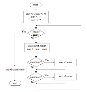
Figure 1.29: Flowchart for program to find
the minimum, maximum, and average of a list of numbers Loop
No comments:
Post a Comment
Don't be a silent reader...
Leave your comments...
Anu